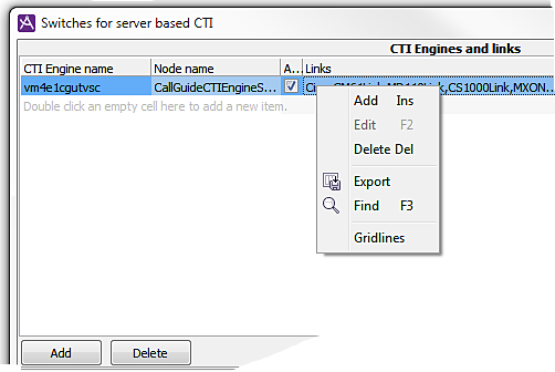
In the upper part of the Switches for server based CTI window, you see CTI engines, their so-called node names, whether the CTI engine should be activated or not, as well as a list of the links connecting the CTI engines with different switches.

Major parts of Telia CallGuide are implemented in the Erlang program language. When nodes are mentioned in this section, this means so-called Erlang nodes.
A ticked checkbox under menu header Activated indicates that the current CTI engine shall be active.
For planned maintenance work you can uncheck the CTI to be prepared for inactivation, i.e. not allow new logins. To know when a server is ready to be inactivated, when the number of logged in agents to a CTI engine is zero, you can check in CallGuide Pulse.
When the CTI engine is ready for activation again, you tick the check box once more to allow logins again.
Each CTI engine communicates with switches via so-called links. The same link name that is used at configuration of CTC Server must also be specified in CallGuide Admin.

A link name can consist of up to 15 characters, upper case and lower case letters A-Z, figures 0-9, and underscore _.
If you have entered a link name earlier, you can see this in an editable drop-down menu). You can enter a new link name, but you also have the option of picking a link name from the list. If you pick an existing link name, the switch that the earlier link with this name, is connected to, will be default. If you are using Centrex IP or Touchpoint Plus PBX type, you see another four columns, where you shall enter the IP number and port number used to connect to Telia Company’s gateways, both a primary number, and the one to be used as fallback, if the primary number is not available.
When a CTI engine is removed, the links to it disappear as well. However, the link names remain in the list of link names until deleted manually.
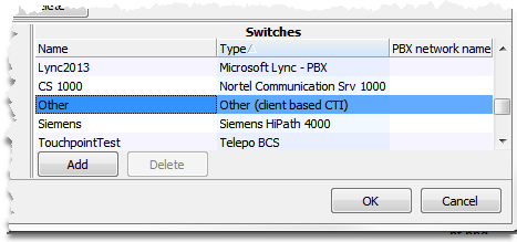
At the bottom right of the Switches for server based CTI window you see configured switches, with the name and switch type for each switch as well any net group affiliation.

Switches can be added with optional names, and existing names can be modified or removed. If you are using Telia Touchpoint Plus as PBX the name must match what has been configured in CallGuide Service Node and CallGuide Service Engine. If you are using Microsoft Lync as PBX you should start with reading Specific configuration of the Microsoft Lync PBX type.
The PBX types picked from a drop-down list to the right are pre-defined and cannot be changed or removed.
To be able to call internally between several PBXs’ extensions locations, with extension numbers according to a shared number plan, these PBXs must belong to the same so-called net group. This is how you proceed to create a net group:
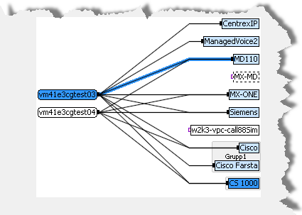
At the bottom left of the Switches for server based CTI window, you see a drawing of all the CTI engines, and switches in your CallGuide system, as well as the links connecting them.

What is selected in the other parts of the window are seen marked in the picture. This means that the CTI engine selected at the top left is seen in a darker shade to the left in the picture. The link selected to the right, is seen as a darker line between the CTI engine and the switch. The switch marked under the Switches heading, is seen marked in the same way in the right part of the overview.
Links and switches that can be used by the selected CTI engine are seen in the picture by a softer shade of the marking colour. Exactly which marking colour you see, is ruled by the colour theme in your computer’s Windows settings.
Other graphical features are:

|
A black connection point shows that this (selected) CTI engine is connected while a reddish unfilled connection point indicates that a CTI engine does not have any links toa ny PBX.. |
|
|
A reddish unfilled connection point indicates that there are no links to this switch. |
|
|
A switch that is not in use, or has not yet been connected, is seen by a broken contour. You are allowed to remove it… |
|
|
The green colour of the link (line) indicates that the switch isnew, but not yet saved in the database. The text in the column’s link name is green as well. |
|
|
A CTI engine that is being removed is seen in grey until you have clicked on OK to save this in the database. Since the links are removed as well, the connection point is unfilled. |
|
|
If you, at the bottom right part of the window have sorted by net groups, you can, in the bottom lefter part of the window see the switches that are included in a net group, having a common grey background colour. |
The tables in the Switches for server based CTI window are so-called standard tables, meaning that sorting, finding, and filtering functions are available. At sorting, or filtering, the overview picture is updated correspondingly, meaning that you only see the CTI engines and switches that you can see in the tables, in the overview picture.
The actual technical status, if a link is active or down, is seen in CallGuide Pulse, the CTI Engines and links window.